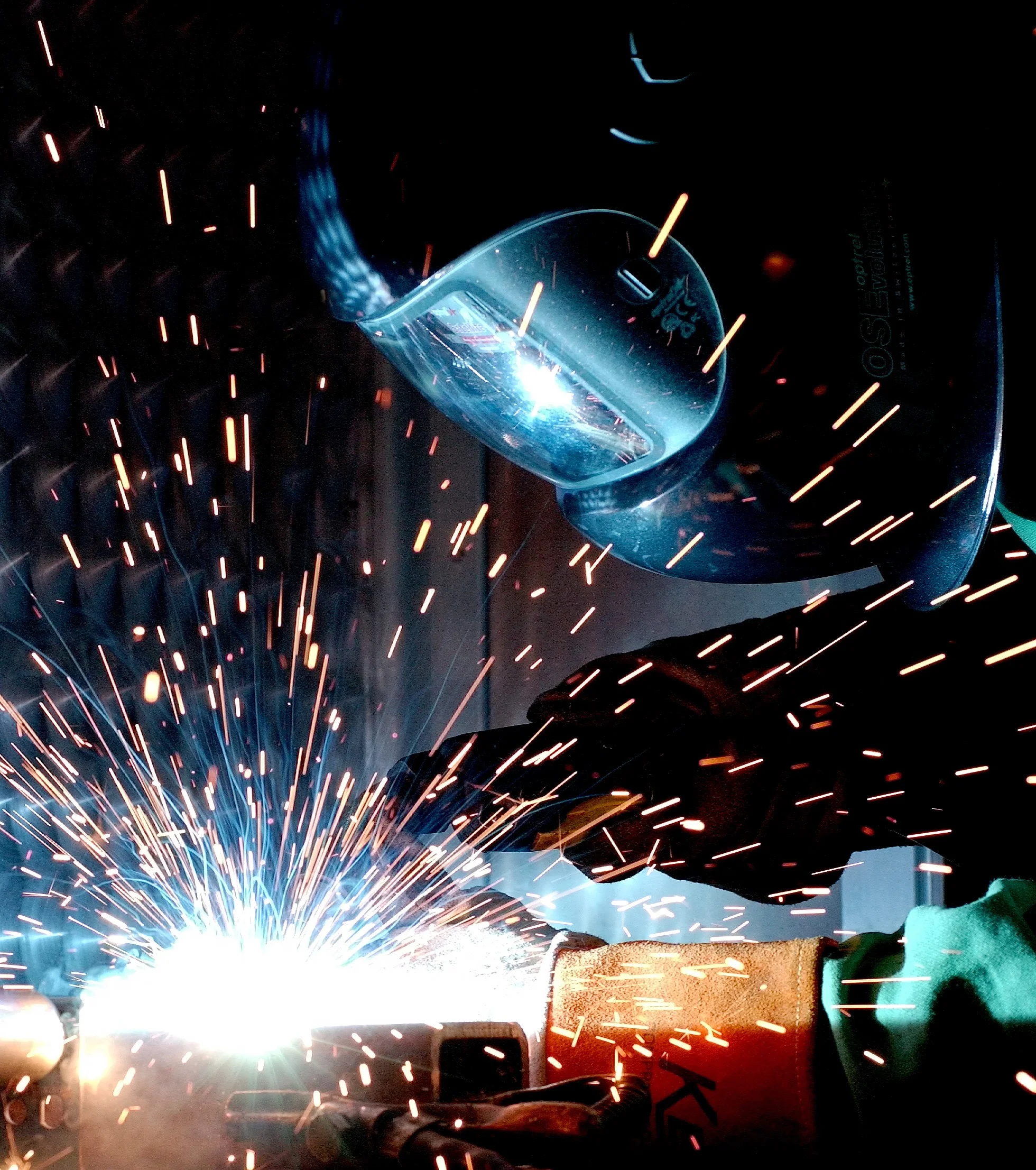
Material Shrinkage Properties in Welding - How Are Weldments Affected by Heat?
Resources:
Miller Welding: https://www.millerwelds.com/resources
American Welding Society: http://www.aws.org/
Arc welding is the process of joining metals using the heat generated from an electric arc, requiring a grounding wire and an electrode. Conventional arc welding uses fluxes to shield the molten metal from becoming contaminated by the atmosphere around the weld (shielding from imperfections, primarily porosity). Inert gas welding, though, uses gases such as argon, helium, and carbon dioxide to shield the weld. It is common in some welding procedures to use a flux-core welding wire in conjunction with inert gas.
Tungsten Inert Gas (TIG) Welding
In TIG welding, also known as Heli-arc welding, a non-consumable tungsten electrode delivers current and creates the welding arc. The welding arc heats up the workpiece, melting the working area, as gas and filler metal is supplied. The gas supply, generally argon or helium, protects the tungsten and weld puddle from contamination.
The welding torch consists of a ceramic cup used to direct the gas flow, a tungsten electrode, and a collet assembly used to hold the tungsten electrode and supply gas. The filler metal is added separately, allowing for direct control over the speed and size of weld operation.
TIG welding generally requires a lot of heat to perform as it melts a puddle along the working joint, resulting in a slower welding process. In doing so, the weld is stronger and more corrosion resistant than other welding techniques but causes more deformation and material shrinkage.
Metal Inert Gas (MIG) Welding
MIG welding uses a consumable electrode that delivers current and creates the welding arc to the workpiece. The continuous solid wire electrode is fed through the welding gun and also acts as the welding wire.
Similarly to the TIG welding process, a shielding gas is used to protect the weld pool from contamination. Because MIG welding allows you to set the speed of the automatic wire feed as well as the amperage, it is generally thought of as an easier form of welding compared with TIG.
The weld placed on the workpiece using a MIG machine often lays cold in the beginning before the base material is able to heat up. Therefore, it is generally more suitable to weld longer joints in unconstrained areas. Starting and stopping will generate an inconsistent weld.
Prediction of Material Shrinkage
Transverse shrinkage is generally much more prevalent than longitudinal shrinkage and is caused by the expansion and contraction of the workpiece as well as the shrinkage of the weld material after the molten puddle cools.
The workpiece can be split into two different areas, the near field – directly affected by expansion and contraction near the welded joint; far field – non-directly affected by welded joint. As the workpiece joint heats up, the near field begins to expand and accepts the weld material. The welded joint cools as the torch moves away from the heat affected zone and contracts as it cools, thickening the workpiece at and around the weld joint.
By Wizard191 - Own work, CC BY-SA 3.0, https://commons.wikimedia.org/w/index.php?curid=8686539
By Wizard191 - Own work, CC BY-SA 3.0, https://commons.wikimedia.org/w/index.php?curid=8686634
N. R. Mandal references multiple theoretical proofs focused on detailing the approximate shrinkage of an unconstrained workpiece in his book, Aluminum Welding. Using the above assumption, he is (in basic terms) able to turn the workpiece into a bar and an elastic spring, offering a theoretical explanation of what is happening to the workpiece.
In each weld case, the material and heat properties are used in conjunction with the setup and weld size. For a butt weld, the shrinkage is variable based on the thickness of the workpiece, the depth of penetration, and the original root gap of the butt joint. For a fillet weld, the shrinkage is variable based on the thickness of the web, thickness of the base workpiece, and the number of weld passes.
By calculating the theoretical shrinkage and deflection of the part, determining the working setup including constraints and deflection compensation is easier.
Finite Element Analysis
For large and small weldment assemblies, it may be necessary to perform finite element analysis (FEA) using computer models to predict deformation at each step. FEA is the process of approximating engineering solutions (structural analysis, heat transfer, fluid flow, etc.) throughout a 3d object or surface by breaking up a model into a 2d or 3d mesh of small areas to accurately represent complex geometry.
In many welding and design companies, it is common for a designer to ask an experienced welder their opinion on how to weld a proposed design to both reduce deflection and shrinkage while keeping the cost and complexity down.
This is a great starting point and will provide valuable insight into how the FEA model should be conducted. Further development of the model at different assembly points while testing for theoretical design specifications is likely needed before physical prototype testing can commence.
Jarrett Linowes
Mechanical Engineer
omniamfg@gmail.com
Did I miss anything you are interested in? Send me an email or comment below!


