How to Calculate Maximum Fastener and Screw Torque
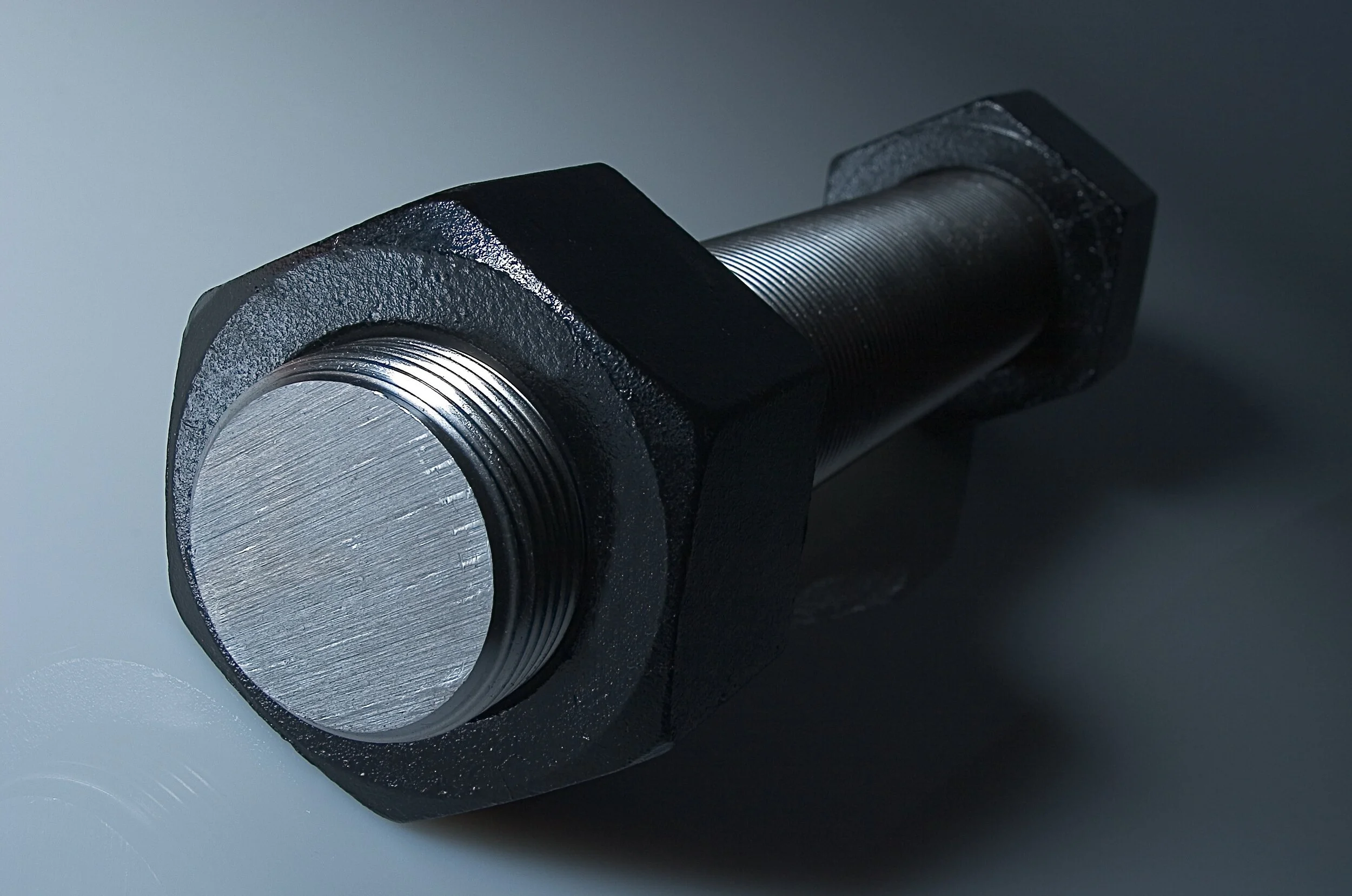
A bolted joint is the joining of two pieces of material using a bolt (or other threaded fastener) and a nut or threaded/tapped hole. It is expected that the bolted joint will be able to withstand the maximum applied forces to the joint over its lifetime.
When designing a bolted joint, it is important to consider the type of fastener used as well as the interior threads of the hole (external and internal threads respectively) based on the expected maximum axial forces that will be applied to the joint in the future. The preload of a bolted joint is the initial axial force applied by the fasteners across the joint. The preload should be equal to or larger than the maximum expected applied axial forces to the bolted joint in order to avoid separation of material.
Preload
The general rule of thumb for bolted joint design (steel fasteners) is for the fastener to be engaged by between 1 and 1.5 times the diameter of the fastener used (softer material fasteners will need a longer engagement length). This rule of thumb is to achieve optimal joint strength.
The preload of a bolted joint design is generally based on the tensile yield strength of the bolt or fastener used. For the calculations in this post, it will be assumed that the yield strength of the internal threads is larger than the proof strength of the fastener threads, causing the limiting factor to be the fastener used. If the internal thread was the limiting factor, additional calculations would be required based on the length of engagement, fastener proof strength, and internal thread yield strength.
The axial preload force of the bolted joint can be calculated as:

Where:
F_AP = Axial Preload Force applied to bolted joint
%_Y = Percent of Yield Strength multiplier
S_YT = Yield Strength of fastener
A_s = Tensile Stress Area of fastener threads
The axial preload force applied to the bolted joint is based on the tensile stress area of the fastener threads. This is calculated from the thread tensile stress area equation detailed in ASME B1.1-2003 Appendix B-1:
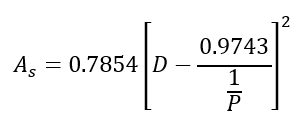
Where:
D = Nominal diameter of the fastener
1/P = Number of threads per inch of the fastener (P = 1/TPI)
More information regarding how this formula came to be can be found in the ASME B1.1-2003 document. The rounded decimals are based on the thread angle, pitch diameter, and pi.

Figure 1: Tensile stress-strain diagram detailing the ultimate tensile strength, yield strength, proof load, and typical axial force on a bolted joint (clamp load).
The proof strength is the limit of the elastic range of the bolt, the point on the curve at which the deformation begins to hold even after the load is reduced. The proof strength can be calculated conservatively as:

Where:
S_P = Proof Strength of the fastener
From this logic, according to mechanical engineering industry agreement, a conservative preload force for a nonpermanent bolted joint can be calculated as:
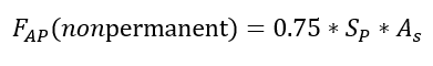
And for a permanent bolted joint:

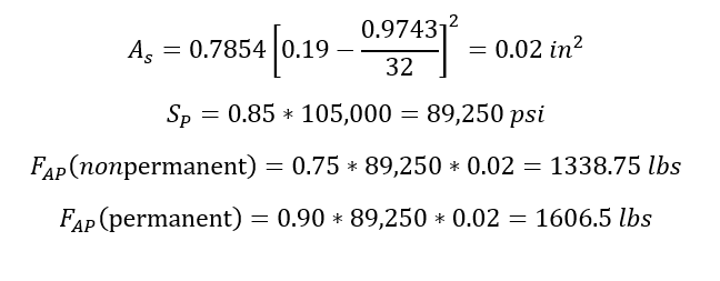
Example:
For a 10-32 bolt made out of A286 with a yield strength of 105 ksi:
Torque
The torque acted on a fastener required to create the preload force is calculated as:

Where:
T = Torque acted on the fastener
D_n = Nominal Diameter of the fastener
F_AP = Axial Preload Force applied to the bolted joint
K_T = Coefficient of Torque
The coefficient of torque is a calculation based on the condition of the fastener and can be affected by lubrication, plating, anti-seize compounds, etc. The coefficient of torque can be estimated as 0.2 if the condition is unknown.
Example:
To continue the example above assuming an unknown joint condition:

If it was known that the bolt would be lubricated, the coefficient of torque would change to some value between 0.16 and 0.18 depending on the lubrication and is based on the coefficient of friction that is used to determine the coefficient of torque.
Jarrett Linowes
Mechanical Engineer
omniamfg@gmail.com
Did I miss anything you are interested in? Send me an email or comment below!